
High-precision air flow sensors transform HVAC systems from static, energy-wasting utilities into dynamic, responsive assets. By replacing estimated damper positions with actual velocity data, these sensors eliminate the “performance gap” in Demand-Controlled Ventilation (DCV) and Heat Recovery systems. They prevent catastrophic core freezing in cold climates, ensure regulatory air quality compliance without over-ventilation, and reduce HVAC energy consumption by 25–40% by allowing operators to condition only the exact volume of air required.
Sector: Building Automation & HVAC
Subsector: Energy Recovery Ventilation (ERV) and Demand-Controlled Ventilation (DCV)
Target Product: High-Precision Air Flow Sensor (Velocity & Volumetric)
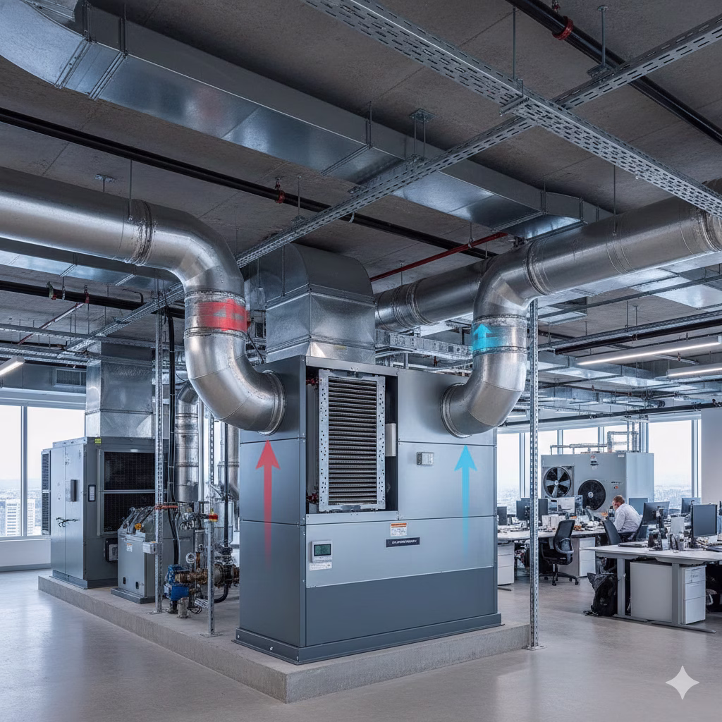
The Air Flow Sensor is the critical feedback mechanism in modern air handling architectures, providing the real-time velocity data necessary to close the control loop between biological demand (CO2/Occupancy) and mechanical supply (Dampers/Fans).
💡 What Operational Challenge Defines This Application?
Why is “Good” Ventilation So Difficult to Achieve?
The fundamental challenge in modern HVAC—specifically within Total Heat Exchange and Demand-Controlled Ventilation systems—is the conflict between Indoor Air Quality (IAQ) and Energy Efficiency.
In a “dumb” system (Constant Air Volume), fans run at a fixed speed. This ensures safety but wastes massive amounts of energy heating or cooling outdoor air when the building is partially empty. In “smart” systems, the goal is to modulate airflow based on occupancy. However, the environment is hostile and non-linear. Duct pressure fluctuates, filters clog, and outdoor temperatures swing wildly.
“Good performance” is defined as delivering the exact cubic feet per minute (CFM) of fresh air required by ASHRAE standards—no more, no less—while recovering thermal energy from exhaust air. Achieving this requires the system to balance intake and exhaust flows perfectly. If this balance breaks, the building suffers from negative pressure (sucking in unconditioned air/pollutants), energy waste, or, in cold climates, the catastrophic freezing of heat exchange cores.
🛠️ What Are the Primary Application Challenges & Pain Points?
1. The “Damper Position” Fallacy (Control Instability)
Root Cause: Most legacy systems assume that a damper open at 50% allows 50% airflow. This is false. The relationship between damper angle and airflow is non-linear and changes based on system pressure.
Operational Consequence: The Building Management System (BMS) tries to adjust ventilation but “hunts” or oscillates—constantly opening and closing dampers to find the right setpoint. This causes rapid cycling of fans and chillers, leading to premature equipment failure and unstable room temperatures.
Affected Stakeholders: System Integrators (programming difficulty), End Users (noise/comfort), Operators (maintenance costs).
2. Heat Exchanger Core Freezing & Blockage
Root Cause: In Total Heat Exchange systems operating in sub-10°C (50°F) weather, humidity in the exhaust air stream condenses and freezes upon contact with the cold intake air within the core.
Operational Consequence: Ice blocks the airflow channels. The system loses its ability to recover heat, and eventually, the fresh air supply is choked off entirely. Traditional “defrost” cycles (electric heaters or bypassing the core) destroy energy efficiency.
Affected Stakeholders: Operators (system downtime), End Users (loss of ventilation).
3. The “Over-Sizing” Trap (CapEx Bloat)
Root Cause: Without accurate flow measurement, engineers cannot trust the system to ramp up quickly enough for peak loads. Therefore, they size chillers, boilers, and fans for the “worst-case scenario” (100% occupancy) rather than realistic diversity factors.
Operational Consequence: Building owners pay for massive infrastructure capacity that sits idle 90% of the time. Additionally, oversized equipment operating at low loads is notoriously inefficient.
Affected Stakeholders: OEMs (pressure to reduce unit footprint), Investors/Owners (inflated capital expenditure).
4. Regulatory & Safety Non-Compliance
Root Cause: CO2 sensors measure air quality, but they do not measure air volume. A low CO2 reading might mean the air is clean, or it might mean the sensor is drifting.
Operational Consequence: Without a flow sensor verifying actual intake rates (CFM), operators cannot prove they are meeting minimum ventilation codes (e.g., ASHRAE 62.1) for VOC dilution.
Affected Stakeholders: End Users (health risks/Sick Building Syndrome), Operators (liability).
⚙️ Implications for Manufacturers of the Target Product
For a sensor manufacturer, these pain points dictate strict engineering requirements. A generic sensor is insufficient for these critical control loops.
- Low-Velocity Sensitivity is Non-Negotiable: The sensor must maintain high accuracy (<2% error) at very low velocities (down to 250 fpm). This is critical because energy-efficient systems spend most of their time in “low-flow” states.
- Environmental Hardening: The sensor sits in the air stream. It must resist fouling from dust and withstand high humidity/condensation without drift, particularly in the exhaust stream of a heat exchanger.
- Response Time: To prevent “damper hunting,” the sensor must provide near-instantaneous feedback to the controller. Latency induces oscillation.
- Integration: The output must be easily digestible by standard controllers to calculate volumetric flow (Area times Velocity) dynamically.
✅ How Does the Target Product Solve These Problems?
Mechanistic Resolution of Pain Points
1. Decoupling Flow from Pressure (Solving the Damper Fallacy)
The air flow sensor provides a direct variable measurement. Instead of telling a damper to “go to 50%,” the controller tells the damper to “open until Flow = 500 CFM.” The sensor closes the loop. If filters load up or wind pressure changes, the sensor detects the flow drop, and the damper adjusts automatically. This eliminates “hunting” and stabilizes the entire HVAC plant.
2. Precision Anti-Freeze Mixing
In cold climates, the sensor enables a sophisticated “recirculation strategy.” Instead of using expensive electric heaters, the system mixes a precise amount of warm indoor return air with the cold outdoor air before it hits the heat exchanger.
- The Gain: The sensor ensures the mix is exactly warm enough to prevent freezing, but no warmer, maximizing the amount of fresh air while protecting the hardware. This turns a binary “defrost” mode into a continuous, efficient operating state.
3. Validated Demand-Controlled Ventilation (DCV)
By combining CO2 data (demand) with Flow data (supply), the system becomes fully verifiable. The sensor ensures that when occupancy drops, the ventilation rate drops proportionally, saving 25–40% on fan and thermal energy. Crucially, it maintains a “hard floor” of minimum airflow to manage non-human pollutants (VOCs from furniture/carpets), which CO2 sensors alone cannot detect.
4. CapEx Reduction (Right-Sizing)
When OEMs can prove that their air handling units react instantly to load changes via accurate flow sensing, they can justify using smaller heating/cooling coils and electrical services. The system is sized for actual dynamic load, not theoretical peaks.
⚖️ Alternative Solutions & Engineering Tradeoffs
Buyers often consider cheaper alternatives, but they introduce significant operational risks.
| Alternative Approach | Mechanism | Limitation/Tradeoff |
|---|---|---|
| Damper Position Feedback | Uses the actuator’s angle to estimate flow based on a lookup table. | High Inaccuracy: Fails to account for filter loading, wind pressure, or duct leakage. Leads to significant energy waste. |
| Constant Air Volume (CAV) | Mechanically fixed regulators that maintain a specific flow rate. | Zero Flexibility: Cannot adjust for occupancy. The building is ventilated for 1,000 people even if only 5 are present. |
| Pressure Transducers | Measures static pressure drop across a component (like a coil) to infer flow. | Maintenance Heavy: Pressure ports clog easily; the relationship between pressure and flow degrades as coils get dirty. |
| Temp-Based Defrost | Uses temperature sensors to trigger a full bypass or heater when cold air is detected. | Energy Inefficient: Reactive and binary. Usually over-corrects, dumping valuable heat or consuming excess electricity. |
📈 Business & Market Implications
The Shift from “Component” to “System Performance”
The market is moving away from buying “fans and dampers” to buying “verified air quality and efficiency.”
- Regulatory Pressure: Codes like ASHRAE 62.1 and certifications like LEED require verification of ventilation rates. You cannot verify what you do not measure. This makes flow sensors a compliance necessity, not just a luxury.
- The “Green” Premium: Building owners are increasingly sensitive to OpEx. A system that saves 30% on energy bills by using accurate flow data has a much shorter payback period (ROI) than a cheaper, dumb system.
- Retrofit Potential: There is a massive market in retrofitting existing buildings. Installing flow sensors into legacy ducts allows modern control strategies without replacing the heavy iron (fans/chillers).
🗺️ Opportunity Map for Manufacturers of the Target Product
a. High-Value Application Scenarios
- Cold-Climate Heat Recovery: Regions where winter temps drop below freezing. The sensor is the only way to run heat exchangers reliably without expensive auxiliary heat.
- High-Occupancy Variance Spaces: Theaters, schools, and conference centers. Occupancy swings from 0% to 100% rapidly. Only flow sensors can track this dynamic demand efficiently.
- Laboratory/Healthcare: Critical environments where pressure relationships (positive/negative rooms) must be maintained for safety.
b. Priority Pain Points to Target
- “The Phantom Energy Bill”: Target the hidden cost of over-ventilation in variable occupancy buildings.
- “The Frozen Core”: Target the maintenance nightmare of heat exchanger damage in winter.
- “The Compliance Gap”: Target the inability of current systems to prove they are meeting fresh air codes.
c. Product Improvement Opportunities
- Self-Cleaning/Dust Resistant: Develop probe geometries that resist particulate buildup to reduce maintenance cycles.
- Integrated Wireless: Retrofitting sensors is expensive due to cabling. A reliable wireless flow sensor would dominate the retrofit market.
- Low-Flow Accuracy: Push the lower limit of detection. Systems are getting more efficient and moving air slower; sensors must keep up.
d. Buyer Guidance (For OEMs & Integrators)
- Look for Turndown Ratio: Ensure the sensor is accurate at 10% of system capacity, not just 100%.
- Verify “Installed Accuracy”: Lab accuracy differs from duct accuracy. Choose sensors that are forgiving of poor placement (e.g., near bends).
- Value the Feedback Loop: Do not rely on CO2 sensors alone. A CO2 sensor asks for air; the Flow sensor confirms it arrived. You need both.
e. Strategic Takeaways
The Air Flow Sensor is not a passive gauge; it is the governor of efficiency. For manufacturers, the narrative must shift from “we measure air” to “we enable the $40\%$ energy savings promised by your control algorithm.” Without this component, the smartest BMS is effectively blind.
About the Author
This report was synthesized by GrowthBeaver’s AI, configured to simulate an Application Engineer. By analyzing ASHRAE standards, thermodynamic principles, and market feedback loops, the AI constructs content that bridges the gap between Product Features and Business Value.